MIDI protocol
Principle
Pickup
Frets and strings
Power
Analog part
PIC16x74
COM-port
MIDI-port
Control and indications
Algorithm of note detection
Analog part
Analog part of the scheme consists of six identical channels, one for each string. Opamp K1401UD2A (4 channels) is used to amplify source signal from pickup. Then amplified signal is feeded to full rectifier K140DA1 (2 channels). Rectified signal is evened on RC-chain and comes to microcontroller's analog input, and analog-digital conversion is performed.
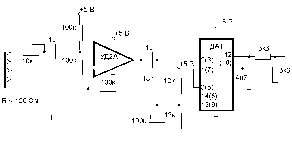
a) Unipolar power
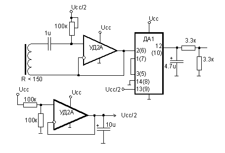
b) Bipolar power
c) Advanced detection using maximum of signal
At first, unipolar scheme (a) was implemented. It leaved 2 channels of Opamp free. After reconstruction the scheme for bipolar power it became more plain and efficient (b).
The principle of evening of output signal (a,b) had a significant imperfection, which caused trouble in detection of notes: evening capacitor did discharge too slow. As a result, when string began to oscillate, ADC saw the exact front of signal (sampling period is approx. 8 ms), but when guitarist muted the string, the signal drop was not so clear, merely 1-2 conversion units per period. Such changes in signal level are common during normal sound of the string too, therefore microcontroller was forced to analyse 5-7 samples of signal to decide if it really is a signal drop or not. Due to guitarist could at the same time additionally change a fret on which a string is pressed to, the algorithm became too complicated. And it was impossible to lower the value of resistor in evening chain because of demands to power consumption.
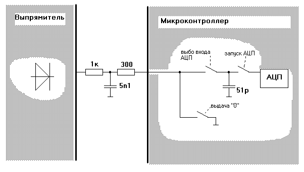
As a result of long thoughts I find an idea - to refuse evening circuit and turn to accumulating circuit, which works like japanese garden-toy "pour-in - pour-out". The principle is shown of Fig.C. When accumulation is in progress, the capacitor have no discharge circuit and is charged up to maximum output value of rectifier over a period of accumulation. After that, before AD conversion, the charge is poured out to analog latch of microcontroller's ADC which is 100 times less in capacitance than accumulative capacitor. After completion of AD conversion the pin of microcontroller, just used as analog input, is reconfigured as digital output and "0" level is set on it. It causes accumulative capacitor to be discharged. After period of time the pin is reconfigured as analog input again (high impedance), and the cycle of accumulation repeats.
This improvement allowed to simplify the algorithm of analyse significantly. As a fact, now it is possible to examine only present and previous sample of input signal, without taking in view 5-7 sample history of it.
d) Conditionally working scheme with non-linear amplification (without rectifiers)
The last scheme (d) is an attempt to make amplification of input signal from pickup non-linear, diminishing along with raising the signal itself (dynamic range compensation). At the same time it allows to refuse from rectifier ICs and lower down power consumption again.
The need of dynamic range compensation is conditioned by the fact that if the loud sounding string will be striken fast by finger or mediator, the amplitude of amplified signal will be up to (or above) limit all time (without significant dip) and the microcontroller will be unable to detect new note. And it is impossible to lower gain because this will cause fail to detect soft notes.
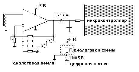
Signal rectification is achieved owing to return to unipolar power. Accumulating capacitor is discharged by software shortening the microprocessor's pin to the ground as before.
Unfortunately, this scheme is not working, i.e. it works under condition: the own bias of opamp shound be positive. Otherwise it is not possible to amplify weak input signal below own bias - it will result in negative output voltage (really ground level will be on output). Negative own bias should be compensated by external pull-up of input, but I still not realized how to implement it beautifully, e.g. with one resistor. But I managed to select 2 of 5 opamps which has positive own bias of the required channels.